


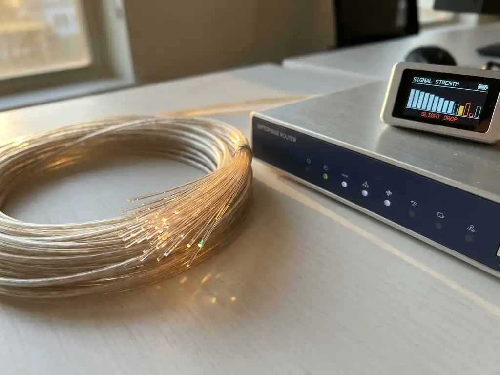
Fiber optic signal loss of 5–10% is considered normal for professional connections and is an unavoidable result of optical attenuation, connector losses, and cable length. Understanding what drives this signal degradation, and recognizing when it crosses into problematic territory, is essential for IT managers and network engineers responsible for business-critical infrastructure. This article explains the technical causes of fiber optic signal loss, provides concrete dB loss benchmarks, defines the thresholds at which loss becomes a performance risk, and outlines practical steps to diagnose and minimize it.
What is normal speed loss for a fiber optic connection?
For a professional fiber optic connection, a speed loss of 5–10% is acceptable under normal conditions. This loss is caused by the physical properties of light transmission through fiber optic cable and is technically unavoidable.
Fiber optic signal loss results from several factors inherent to optical transmission. Light signals naturally attenuate over distance, even in high-quality fiber. In addition, connectors, splitters, and couplers introduce minimal losses that accumulate across the entire connection.
For most business applications, network performance remains excellent within these normal loss margins. A 1 Gbps fiber connection losing 50–100 Mbps still delivers superior bandwidth compared to traditional copper connections.
The quality of your internet speed over fiber also depends on end-user equipment and network configuration. Modern optical connections largely compensate for natural signal attenuation through advanced transmission technologies.
What causes fiber optic signal loss in business networks?
Signal attenuation, connectors, splices, and cable length are the primary causes of fiber optic signal loss in business networks. These technical factors affect light transmission and, consequently, the overall network performance of your connection.
Optical attenuation occurs when light signals weaken during transport through the fiber optic cable. This natural phenomenon is influenced by the quality of the fiber, bends in the cable, and the wavelength of the light used. Longer distances result in greater attenuation.
Connectors and splices introduce insertion loss at each connection point. Each connector can cause 0.1–0.5 dB of loss, while splitters divide the signal across multiple outputs. Dirty or damaged connectors significantly increase these losses.
Environmental factors such as temperature fluctuations, mechanical stress, and the bend radius of the cable also contribute to signal degradation. Extreme temperatures can alter the refractive index of the fiber, resulting in higher losses.
The quality of active components such as transceivers, switches, and routers also determines final performance. Outdated or unsuitable equipment can create bottlenecks that negate the advantages of fiber optics. A well-designed networking infrastructure helps eliminate these bottlenecks and ensures consistent throughput.
Understanding fiber optic signal loss: dB loss budget explained
Fiber optic signal loss is measured in decibels (dB), a logarithmic unit that expresses the ratio between transmitted and received optical power. The lower the dB value, the less signal degradation your link experiences. Two key measurement concepts apply here: insertion loss, which describes the power lost as light passes through a connector, splice, or other component, and return loss, which describes how much of the signal is reflected back toward the source. Both values matter when assessing the health of a fiber optic link.
Every fiber optic link has an optical loss budget: the maximum total dB loss a connection can sustain while still meeting its performance requirements. Staying within this budget is what separates a reliable link from one that produces errors, retransmissions, and throughput degradation. Understanding the contribution of each component helps you identify where losses accumulate and where intervention is most effective.
How optical attenuation is measured
Optical attenuation is expressed as dB per kilometer (dB/km) for cable segments, and as a fixed dB value for discrete components such as connectors and splices. A well-calibrated optical time-domain reflectometer (OTDR) can measure attenuation along the entire length of a fiber run, pinpointing the exact location of elevated loss. For individual connectors and patch panels, an optical power meter combined with a light source provides a direct insertion loss measurement. These tools are standard in professional network commissioning and fault diagnosis.
When reviewing measurement results, compare them against the manufacturer specifications for each component and against the total optical loss budget for the link. A single component reading outside its expected range is often sufficient to explain broader performance issues across the connection.
Acceptable dB loss values per component
The following reference values reflect widely accepted industry benchmarks for typical fiber optic components. Single-mode fiber cable introduces approximately 0.3–0.4 dB of attenuation per kilometer, making it well suited for long-distance runs. Multi-mode fiber cable has a higher attenuation rate of approximately 2–3 dB per kilometer, which is why it is used for shorter distances. A fusion splice, where two fiber ends are permanently joined by heat, typically adds approximately 0.1 dB of insertion loss. A mechanical connector, such as an LC or SC type, adds between 0.1 and 0.5 dB depending on quality and cleanliness. A patch panel connection introduces approximately 0.5 dB per connection point.
To calculate your total optical loss budget, add the dB contributions of every component in the link: the cable run, each splice, and each connector. If the cumulative total approaches or exceeds the loss budget specified by your transceiver or active equipment, signal quality will deteriorate. Keeping a record of these values during installation makes it significantly easier to diagnose performance changes later.
Single-mode vs. multi-mode fiber: how cable type affects signal loss
The type of fiber optic cable you deploy has a direct impact on how much signal loss accumulates over distance. Single-mode and multi-mode fiber differ fundamentally in core diameter, light propagation behavior, and attenuation rate. Choosing the right type for your environment is one of the most consequential decisions in fiber optic infrastructure planning.
Single-mode fiber (SMF): lower attenuation over long distances
Single-mode fiber uses a very small core diameter of approximately 9 micrometers. This narrow core allows only a single light mode to propagate, which eliminates modal dispersion and results in very low attenuation: typically 0.3–0.4 dB per kilometer. Single-mode fiber is suitable for distances up to 40–80 km without amplification, depending on the transceiver and wavelength used.
For business use, single-mode fiber is the standard choice for campus backbone connections, inter-building links, and connections to carrier infrastructure. Its low signal loss profile means that even over long runs, the cumulative dB loss remains well within the optical loss budget of modern transceivers. If your organization operates across multiple buildings or connects to a data center at distance, single-mode fiber is the appropriate choice.
Multi-mode fiber (MMF): optimized for shorter enterprise runs
Multi-mode fiber uses a larger core diameter, typically 50 or 62.5 micrometers, which allows multiple light modes to propagate simultaneously. This produces higher attenuation of approximately 2–3 dB per kilometer and limits the practical distance to 300–550 meters, depending on the specific fiber grade and the data rate being transmitted.
Within data centers and equipment rooms, multi-mode fiber remains a practical and cost-effective option for short runs between switches, servers, and patch panels. However, deploying multi-mode fiber on a run that exceeds its recommended distance is itself a direct cause of elevated signal loss and degraded throughput. If your infrastructure has grown beyond its original design boundaries, a professional assessment of your fiber type versus your current distance and bandwidth requirements is a logical first step before investing in active equipment upgrades.
Ready for the next step?
Explore our solutions or get in touch with one of our experts directly.
When does speed loss become a problem for your organization?
Speed loss becomes problematic when it exceeds 15–20% of the contracted speed or when business-critical applications respond slowly. Frequent connection drops and inconsistent performance are clear warning signs.
Performance indicators that warrant attention include increased latency, packet loss, and fluctuating bandwidth. When video conferences stutter, cloud applications load slowly, or file transfers take an unacceptably long time, productivity is directly affected.
Acceptable performance thresholds vary by organization and application. For standard office work, 80% of the contracted speed may be sufficient, but critical processes such as real-time data processing or medical imaging require consistent, high performance.
Monitoring your network infrastructure helps identify issues early. Regular speed tests, latency measurements, and network traffic analysis provide insight into the health of your fiber optic connection.
Symptoms such as increasing user complaints, slower backup processes, or problems with VoIP telephony point to underlying network issues that require professional diagnosis. In some cases, these issues can also have implications for network security, making timely attention all the more important.
Step-by-step: how to diagnose excessive fiber optic signal loss
If you suspect your fiber optic connection is underperforming, a structured diagnostic approach helps you isolate the cause efficiently. Work through the following steps before escalating to your provider or engaging external support.
-
Run a baseline speed test from a wired device connected directly to the fiber modem. Note the result as a percentage of your contracted speed. This establishes whether the issue originates at the connection itself or within your internal network.
-
Isolate internal network variables. Disconnect all other devices and test again. If performance improves significantly, the bottleneck is inside your network rather than on the fiber link.
-
Check all physical connectors and patch cables. Inspect for dirt, visible damage, or connectors that are not fully seated. Contaminated connectors are one of the most common and easily resolved causes of elevated insertion loss.
-
Compare results at different times of day. Distinguishing between congestion-related loss, which fluctuates with usage patterns, and persistent signal degradation, which remains constant regardless of time, narrows the likely cause considerably.
-
If loss consistently exceeds 15%, document your test results with timestamps. Contact your provider with this data. A structured record of measurements is far more actionable than a general complaint and typically accelerates the diagnostic process on their end.
-
If the provider confirms the line is within specification but internal performance remains poor, assess your active equipment. Switches, routers, and transceivers that are outdated or mismatched to your fiber type can introduce bottlenecks that the fiber link itself is not responsible for.
-
For persistent or complex issues, engage a certified network engineer for an OTDR measurement. An OTDR trace pinpoints the exact location and magnitude of optical attenuation along the fiber run, providing the evidence needed to identify whether the cause is a damaged splice, a faulty connector, or a section of degraded cable.
How can you minimize speed loss with fiber optics?
Professional installation, regular maintenance, and quality control are essential for optimal fiber optic performance. Use high-quality components and ensure connectors are clean and properly aligned to prevent unnecessary losses.
Preventive maintenance includes regular inspection of connectors, checking for cable bends, and cleaning optical interfaces. Dirt and dust are common causes of performance issues that are easily preventable.
Choosing the right active components is critical for fiber optic optimization. Modern transceivers and switches can provide signal amplification and error correction that compensate for natural losses.
We offer professional optical solutions specifically designed for optimal performance in business environments. Our expertise in WDM, DWDM, and xPON technologies maximizes the capacity of your existing fiber optic infrastructure.
For complex network challenges, advanced optical networking products such as DCI solutions and high-performance SFP modules can significantly improve performance. These technologies offer redundancy and optimization for business-critical connections.
Regular performance measurements and proactive monitoring help prevent issues before they affect business operations. A well-designed network infrastructure with professional managed services ensures consistent, reliable fiber optic connectivity.
Frequently Asked Questions
How often should I test the speed of my fiber optic connection?
Test your fiber optic speed monthly during normal business hours and after any changes to your network infrastructure. For business-critical environments, we recommend weekly tests at different times of day to monitor consistency and detect performance trends early.
What are the first steps if my fiber optic connection suddenly becomes much slower?
First, check all physical connections and restart your active equipment (router, switches). Then test the speed directly from the fiber optic modem to rule out whether the issue lies within your internal network. Document when the problem started and contact your provider if the loss exceeds 20%.
Can weather conditions affect the performance of my fiber optic connection?
Extreme weather conditions can indirectly affect fiber optic performance through damage to above-ground infrastructure or temperature fluctuations in equipment rooms. However, underground fiber optic cables are highly weather-resistant. Issues typically arise from power outages affecting active components or damage to connection points.
Which measurement tools are most reliable for testing fiber optic speeds?
Use professional network testing tools or your provider's testing environment for consistent measurements. Run tests from a wired connection, close other internet traffic, and test at different times of day. For business environments, specialized network monitoring solutions offer more detailed analysis of throughput, latency, and packet loss over time.
Is it normal for my fiber optic speed to vary throughout the day?
Minor variations (5–15%) are normal due to network load at your provider and internet traffic in your area. Large fluctuations or consistent slowdowns during specific hours may indicate capacity issues at your provider or internal network bottlenecks that require attention.
When should I consider upgrading my fiber optic infrastructure?
Consider an upgrade when your current connection is consistently loaded above 80%, when new applications require higher bandwidth, or if your equipment is older than 5–7 years. Modern fiber optic solutions often offer better redundancy, lower latency, and support for future capacity needs.
Ready for the next step?
Explore our solutions or get in touch with one of our experts directly.